
Whether you are new to technical moulding or transitioning from machined parts, underestimating Design for Manufacturing (DFM) can lead to expensive consequences. Precision injection moulding requires more than just a 3D model; poor design decisions often result in sink marks, warping, or costly tool modifications that delay production.
At Rediweld, we specialise in supporting customers with DFM at the earliest possible stage. By combining engineering expertise, 3D prototyping, and flexible tooling options, we ensure your component is mouldable, cost-effective, and fit for purpose from day one. This guide explains the fundamentals of technical design support to help you get it right the first time.
What is the Difference Between Standard and Technical Injection Moulding?
Injection moulding is widely used across many industries, but not all moulding projects are the same.
Standard injection moulding generally focuses on high-volume production of relatively simple parts, using commodity plastics such as polypropylene or ABS. Tolerances are often broader and environmental demands less extreme.
Technical moulding, by contrast, is focused on performance-critical components. It often involves tighter dimensional tolerances, complex geometries, functional features, and the use of engineering grade polymers such as Nylon, PEEK, or glass-filled materials. These components may be required to withstand high temperatures, aggressive chemicals, UV exposure, or sustained mechanical loads.
In technical moulding, the design phase is just as important as the production phase. Small geometric details can significantly influence performance, durability, and manufacturability. That is why early Design for Manufacturing in injection moulding is essential.
When Should I Involve a Moulding Partner in the Design Process?
The simple answer is, as early as possible. One of the most common and costly mistakes is finalising a design before confirming that it is suitable for injection moulding. Once a tool is cut in steel, making significant changes can be expensive and time-consuming. Engaging a moulding partner during concept development or at the 3D modelling stage allows potential risks to be identified and resolved early.
At this stage, we can review:
- Material selection
- Wall thickness consistency, which may involve coring out thick sections of material
- Rib and boss design
- Adding draft angles to assist with part ejection
- Gate design, location and material flow
- Likely shrinkage behaviour
Early DFM input reduces development risk, can help to shorten lead times and significantly lowers the likelihood of expensive post-tool modifications.
The Importance of Design for Manufacturing (DFM) in Injection Moulding
Design for Manufacturing (DFM) in injection moulding is the primary technical framework for effective design support. It is a structured engineering review that evaluates how a part will behave during filling, packing, cooling, and ejection.
When molten polymer enters the tool cavity, it must flow evenly and completely before solidifying. If the geometry restricts flow or creates uneven cooling, defects can occur. These may include sink marks, weld lines, voids, warping, or internal stresses.
A thorough DFM review considers:
| Design Element | Why It Matters |
| Wall thickness | Affects cooling rate, shrinkage and cycle time |
| Corner radii | Reduces stress concentrations and improves flow |
| Draft angles | Ensures reliable ejection from the tool |
| Rib placement | Adds strength without excess mass |
| Material grade | Determines shrinkage, strength and chemical resistance |
Early Design for Manufacturing in injection moulding reduces the likelihood of costly tooling changes. Once a steel tool has been cut, altering geometry can require welding, re-machining, or even complete tool replacement. Addressing these issues at the design stage ensures a smoother path to full production and keeps your project on schedule.
What are the Most Common Design Mistakes in Technical Moulding?
Several recurring design issues can compromise both manufacturability and performance.
Sharp Internal Corners
Sharp internal corners create stress concentration points that can reduce fatigue life and increase the risk of cracking. They also restrict polymer flow within the cavity. Having appropriate corner radii improves strength and mouldability. Ideally the molten material wants to flow smoothly into the tool, unhindered by sharp changes in flow direction, so rounded corners (radii) help with this flow.
Lack of Injection Moulding Draft Angles
Draft angles are a taper on vertical walls that help the part eject cleanly from the mould. When injection moulding draft angles are omitted or insufficient, parts can stick in the mould, surface finish can be compromised, and tool wear can increase, all of which lead to production delays and higher costs. This oversight typically happens because draft is not needed for prototyping methods like 3D printing or machining, so it is overlooked until production tooling is attempted.
As a general guideline, at least one degree of draft per side is recommended for many materials, although textured finishes may require more. In some cases the draft angle can be less than one degree, but this will depend on the height of the feature, the material and surface finish. As a last resort if the angle cannot be adjusted then a side action might be employed in the mould tool to achieve the right angle required however this will add complexity and cost to the tool.
Uneven Wall Sections
Inconsistent wall thickness is one of the most common and costly causes of defects in technical moulding. Wall thickness consistency is essential because thick sections cool more slowly than thin ones, leading to uneven shrinkage. This can result in sink marks, warping, internal stress and voids, and extended cycle times.
When a part cools unevenly, internal stresses develop within the material. Over time, these stresses can compromise dimensional stability and long-term durability. In high-precision applications, even slight distortion may affect assembly, sealing performance or functional alignment.
Rather than increasing wall thickness to improve strength, it is usually more effective to incorporate ribs or gussets. These features provide stiffness while maintaining wall thickness consistency, supporting even cooling and predictable shrinkage. If ribs are going to be used, the typical rule is to make the root of the rib 2/3 the thickness of the wall section it is coincident with to help ensure shrink marks do not become a problem.
Addressing wall thickness consistency by designing for uniform wall sections offers several advantages, including reduced visual defects, improved dimensional control, shorter cycle times, lower material usage, and more consistent mechanical performance. In technical moulding, where tolerances are tight and performance is critical, these benefits are particularly important.
How Can I Reduce the Weight of my Components Without Losing Strength?
Reducing component weight is a common goal in sectors such as aerospace, automotive, electronics, and industrial equipment.
Metal to plastic conversion offers a powerful route to weight reduction while maintaining or even improving performance. Replacing a machined or cast metal component with a carefully designed polymer alternative can deliver significant benefits, including:
- Lower overall mass
- Reduced material and machining costs
- Improved corrosion resistance
- Simplified assembly
- Significantly speed up production and parts availability
Engineering grade polymers, especially glass-filled Nylon or high-performance materials such as PEEK, provide excellent strength-to-weight ratios. Glass reinforcement increases stiffness and dimensional stability, allowing thinner sections and lighter parts.
When metal to plastic conversion is supported by carefully considered Design for Manufacturing (DFM) in injection moulding, the result is not a direct copy of the metal part, but a fully optimised polymer design that takes advantage of moulding capabilities.
How Do I Choose the Right Plastic Material for my Environment?
Material selection is central to successful technical moulding. The right polymer must perform reliably under real operating conditions in its intended environment.
For example, components exposed to oils or cleaning agents require materials with strong chemical stability. Parts used outdoors must resist UV degradation. High-temperature environments demand polymers with appropriate heat deflection temperatures. It is also important to consider factors such as mechanical load and regulatory requirements.
Engineering grade polymers provide a wide spectrum of properties. Nylon offers good strength and wear resistance. PEEK delivers exceptional thermal and chemical performance for demanding applications. Glass-filled grades increase stiffness and dimensional stability.
At Rediweld Moulding, material selection forms part of our Design for Manufacturing in injection moulding process. We assess your operating conditions and recommend a polymer that balances performance, cost, and manufacturability. Feel free to reach out with your specific requirements and we will endeavour to match something to your needs.
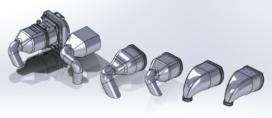
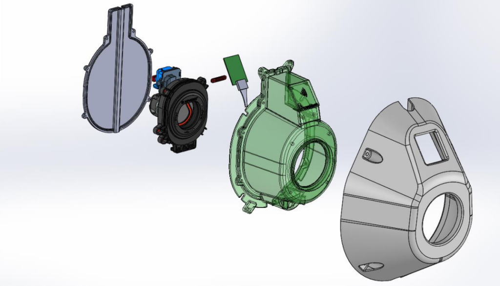
3D Modelling and Prototyping for Fit, Form, and Function
Digital design tools play a crucial role in modern technical moulding. Using SolidWorks 3D modelling, the product of prototypes helps us to evaluate geometry, identify interference issues, and assess assembly compatibility before tooling is produced.
Physical prototypes are invaluable for validating:
- Fit within an assembly
- Functional performance
- Ergonomics and handling
- Visual appearance and aesthetics
3D modelling and prototyping reduce uncertainty and enable informed decision-making. They also support effective metal to plastic conversion projects, where geometry often needs to be re-engineered rather than simply replicated.
By integrating 3D modelling and prototyping into our design for manufacturing in injection moulding workflow, we help ensure a smooth transition from concept to production.
Mould Tooling Options and Production Strategy
Selecting the correct mould tooling options is another critical decision. The most common choice is between aluminium tooling and hardened steel tooling. The right option depends on production volume, expected tool life, how abrasive the material to be used is going to be on the tool surface and budget.
Aluminium tooling, with a lower upfront cost and shorter lead time, can be advantageous for pilot runs, bridge production, or low to medium volumes. Steel tooling, while requiring a higher initial investment and longer-term production, offers durability and consistency for large-scale manufacturing.
During early DFM consultations, we review expected volumes, lifecycle requirements, and budget constraints. This ensures that the chosen mould tooling options align with your commercial objectives.
How to Design Parts for Assembly
A technically sound moulded part must also integrate effectively into the wider product. Designing parts for assembly involves considering how components will be joined, aligned, and secured. Features such as snap fits, moulded bosses, inserts, and alignment pins can reduce part count and simplify manufacturing.
When designing for assembly, it is important to consider:
- Tolerance stack-up across multiple components
- Access for fasteners or automated tooling
- Potential need for secondary machining
- Surface finishing or labelling requirements
- Use of machined metal threaded inserts to help screw the assembly together
Because we offer machining, assembly, and finishing alongside moulding, we review these downstream requirements during Design for Manufacturing in injection moulding. This integrated approach reduces handling, shortens lead times, and improves overall product quality.
Lay the Foundations for Project Success with Design for Manufacturing (DFM) in Injection Moulding
Technical moulding is most successful when design and manufacturing are aligned from the outset. Design for Manufacturing (DFM) in injection moulding is the cornerstone of effective design support, providing a structured framework to ensure your component is mouldable, efficient, and commercially viable before tooling is commissioned.
By addressing factors such as wall thickness consistency, draft angles, and selection of the right engineering grade polymers, potential defects and performance risks can be eliminated at the design stage. Early DFM also supports effective metal to plastic conversion and informed decisions around mould tooling options.
The outcome is fewer tooling modifications, reduced delays, and greater confidence in production readiness. Instead of reacting to problems during trials, you move forward with a design that has already been engineered for manufacture.
At Rediweld, we work with customers from concept to delivery, providing practical, technically grounded guidance at every stage. If you are developing a new product or reviewing an existing design, early collaboration can make the difference between costly redesign and confident, right-first-time production.
Contact our team to discuss how we can support your next technical moulding project.