
You have invested time and budget into developing a new plastic component. The tool is cut, the first shots are moulded, and dimensionally everything looks correct. Yet the surface is not quite right. There is visible flash along the parting line. The gloss level does not match your expectation. Assembly requires a second supplier for welding and a third for printing. Suddenly, a straightforward moulding project becomes fragmented, delayed and more expensive than planned.
This is a common frustration for product designers and engineers. Post-moulding finishing is where many projects lose efficiency, especially when moulding, decoration and assembly are handled in different locations.
At Rediweld Moulding, we address this challenge through a full turn-key approach. From early design advice and tooling through to finishing, assembly and delivery, we manage every stage in-house. That includes specifying injection moulding surface finish standards (SPI vs. VDI), carrying out precise secondary operations in plastic moulding, and delivering fully assembled, branded components ready for market.
This guide explains the key finishing processes, answers common technical questions, and demonstrates how an integrated approach ensures the perfect surface every time.
Why Surface Finish Matters in Plastic Components
The surface finish of a plastic component affects more than just its appearance. Texture and polish influence grip, durability, cleanability and even how a product is perceived by customers. A polished electronics housing signals quality and precision. A textured tool handle improves ergonomics and safety.
Achieving these results requires careful planning during tool design as well as precise finishing processes after moulding. Engineers rely on injection moulding surface finish standards to define the level of gloss, texture and surface quality required for a product.
One of the most widely discussed comparisons within these standards is SPI vs. VDI, two systems used globally to classify mould tool finishes.
Understanding Injection Moulding Surface Finish Standards (SPI vs. VDI)
Injection moulding surface finish standards provide a clear specification for the surface condition of mould cavities. They ensure consistency between design expectations and the final moulded component.
Two standards dominate the industry: SPI and VDI. Engineers frequently discuss SPI vs. VDI when selecting the appropriate finish for a new mould tool.
SPI Surface Finish Standards
SPI standards originated in the United States and are set by the Plastics Industry Association. Widely used across the UK manufacturing sector, they classify finishes into 12 grades, and 4 categories from A to D. A represents highly polished surfaces and D represents rough, blasted finishes, but the table below goes into further detail on the differences between grades.
|
SPI Grade |
Finish Type |
Typical Surface Description |
Method Used |
|
A-1 |
High Gloss |
Mirror finish, optical clarity |
Grade #3 diamond buff |
|
A-2 |
High Gloss |
Very high gloss cosmetic finish |
Grade #6 diamond buff |
|
A-3 |
High Gloss |
Good gloss finish |
Grade #15 diamond buff |
|
B-1 |
Semi-Gloss |
Smooth finish with moderate gloss |
600 grit paper |
|
B-2 |
Semi-Gloss |
Standard smooth moulded finish |
400 grit paper |
|
B-3 |
Semi-Gloss |
Lightly polished finish |
320 grit paper |
|
C-1 |
Matte |
Fine matte texture |
600 grit stone |
|
C-2 |
Matte |
Standard matte finish |
400 grit stone |
|
C-3 |
Matte |
Coarse matte finish |
320 grit stone |
|
D-1 |
Textured |
Satin or dull textured finish |
Dry blast with glass beads |
|
D-2 |
Textured |
Coarse textured finish |
Dry blast with aluminium oxide |
|
D-3 |
Textured |
Very coarse textured finish |
Dry blast with aluminium oxide |
VDI 3400 Finish Standards
VDI 3400, developed in Germany, defines textured surfaces that are primarily produced through controlled machining processes such as electrical discharge machining.
|
VDI Grade |
Approx. Roughness (Ra µm) |
Surface Appearance |
Typical Applications |
|
VDI 12 |
~0.40 µm |
Very fine matte texture |
Cosmetic parts, light texture requirements |
|
VDI 15 |
~0.56 µm |
Fine texture |
Electronics housings |
|
VDI 18 |
~0.80 µm |
Light matte texture |
Consumer product casings |
|
VDI 21 |
~1.12 µm |
Moderate matte texture |
Appliance housings |
|
VDI 24 |
~1.60 µm |
Standard textured finish |
Automotive interiors |
|
VDI 27 |
~2.24 µm |
Noticeable texture |
Tool housings, industrial parts |
|
VDI 30 |
~3.15 µm |
Coarse matte finish |
Functional grip surfaces |
|
VDI 33 |
~4.50 µm |
Heavy texture |
Handheld equipment |
|
VDI 36 |
~6.30 µm |
Very coarse texture |
Rugged industrial components |
|
VDI 39 |
~9.00 µm |
Deep textured surface |
Anti-slip surfaces |
|
VDI 42 |
~12.50 µm |
Very heavy texture |
Heavy-duty industrial parts |
|
VDI 45 |
~18.00 µm |
Extremely rough texture |
Specialised grip or structural surfaces |
What is the Difference Between SPI vs. VDI Surface Finishes?
The comparison table below highlights the main differences in the SPI vs. VDI systems.
|
Feature |
SPI Standard |
VDI 3400 Standard |
|
Origin |
United States, widely used in UK |
Germany, European standard |
|
Focus |
Smoothness and gloss |
Controlled texture roughness |
|
Classification |
A to D grades |
Numerical scale e.g. VDI 12 to VDI 45 |
|
Highest finish |
SPI A-1 mirror gloss |
Fine EDM texture |
|
Typical use |
Cosmetic housings, clear parts |
Grip surfaces, matte finishes |
Injection moulding surface finish standards should be considered at the earliest design stage because they influence the choice of tooling material, machining method, and production cost.
Designers frequently ask us: “does the surface finish affect the cost of the mould tool?”. The answer is yes. Achieving the highest SPI finish requires hardened tool steel and extensive manual polishing using diamond compounds. These processes increase both manufacturing time and tooling expense. A textured finish specified through VDI standards often requires less polishing, which can reduce cost and lead time.
Understanding SPI vs. VDI helps designers balance appearance, performance and budget. At Rediweld Moulding, we guide customers through injection moulding surface finish standards during design for manufacture reviews, ensuring expectations align with budget and application requirements.
Creating the Desired Look and Feel with Surface Texturing and Bead Blasting
Surface appearance is not only about standards but also user experience. The tactile and visual qualities of a component can be refined through surface texturing and bead blasting. These techniques alter the surface of the mould tool cavity so that the finished plastic or rubber part leaves the mould with a specific appearance and feel.
Surface texturing and bead blasting are commonly used to produce matte or satin finishes, improve grip on handheld products, and reduce glare under bright lighting. They can also help conceal minor flow marks or sink areas that may occur during moulding.
Bead blasting is widely used to create consistent matte finishes. Fine media such as glass beads are blasted onto the steel mould cavity, forming a uniform micro-texture that is replicated on every moulded component.
For more defined grain patterns, mould tools can also be chemically etched before production. This process creates controlled textures on the steel surface, which are then reproduced on the moulded part.
By incorporating surface texturing and bead blasting specifications early in tool design, we prevent downstream issues such as sticking or excessive ejection force. Proper tooling design ensures parts release cleanly without damaging the finish.
Secondary Operations in Plastic Moulding
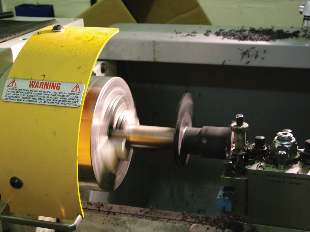
Secondary operations in plastic moulding refer to all post-moulding processes required to transform a component into a finished product. Many manufacturers treat secondary operations as separate contracts. However, fragmentation introduces logistical delays and inconsistent quality control.
At Rediweld Moulding, secondary operations in plastic moulding are managed within the same controlled environment as the moulding process itself. This unified structure improves traceability, reduces handling damage and ensures alignment with original design intent. The following are some of the secondary operations most commonly requested by our customers.
Removing Imperfections with Flash Removal and Gate Trimming
Even with precision tooling, minor finishing may be required after moulding. Flash removal and gate trimming are two of the most common processes used to refine moulded parts.
Flash refers to the thin excess plastic that can appear along the mould parting line. Gate stubs are small remnants left where the molten polymer enters the mould cavity. These imperfections can affect both appearance and assembly if they are not removed properly.
How do you remove flash from injection moulded parts? The method depends on production scale and material type. Manual removal is often used for low-volume runs or delicate components. Automated mechanical systems are better suited to high-volume production because they ensure consistent results and faster processing.
For elastomer components, cryogenic deflashing may be employed. Parts are cooled using liquid nitrogen so the flash becomes brittle and can be removed without damaging the main structure of the component.
By incorporating flash removal and gate trimming into our finishing workflow, Rediweld Moulding ensures components meet both functional and cosmetic standards before leaving production.
Joining Components with Ultrasonic Welding for Plastic Parts
Many products consist of multiple moulded pieces that must be permanently joined together. One of the most efficient techniques is ultrasonic welding for plastic parts.
Ultrasonic welding uses high-frequency mechanical vibrations to generate localised heat at the joint interface. The thermoplastic briefly melts and then fuses as it cools, creating a strong and permanent bond.
A common engineering query is: “When should I use ultrasonic welding instead of adhesives?” Ultrasonic welding for plastic parts offers several advantages:
- The process is extremely fast, with cycle times measured in seconds
- No solvents or curing chemicals are required
- The resulting joint is clean and precise, making it suitable for medical or electronic applications
- Bond strength can equal or exceed the parent material
Compared with adhesive bonding, ultrasonic welding for plastic parts is generally faster, cleaner and more repeatable. Adhesives may still be appropriate where flexibility is required or where joining dissimilar materials, but for thermoplastic assemblies welding is often the superior solution.
We design components with energy directors and joint geometries that optimise weld performance from the outset, integrating this capability into our secondary operations in plastic moulding services.
Strengthening Plastic Parts with Heat Staking and Threaded Inserts
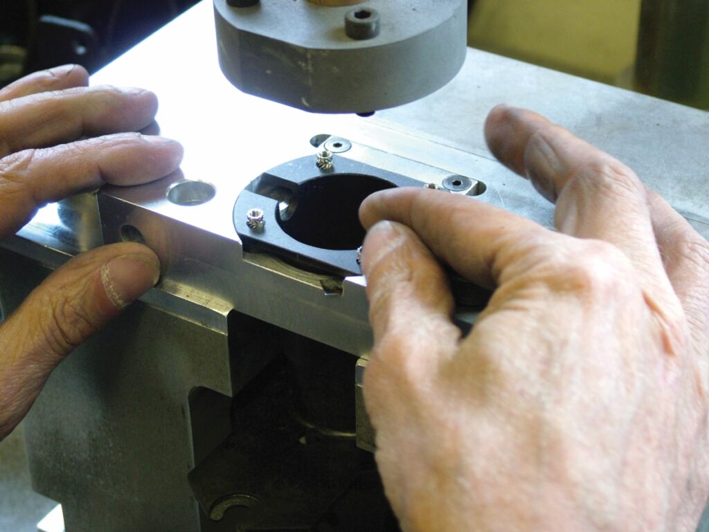
Engineers frequently ask: “Can I add metal threads to a plastic part after it has been moulded?”. The answer is yes, by using heat staking and threaded inserts. These processes allow metal fixings to be installed securely within moulded plastic components.
In heat staking, a metal insert is positioned in a pre-moulded hole and heat softens the surrounding plastic. The material flows around the insert and locks it in place as it cools. Alternatively, ultrasonic insertion can be used, where vibration generates the necessary heat. The result is a strong, durable fixing capable of withstanding repeated assembly cycles.
Heat staking and threaded inserts create durable threads capable of withstanding repeated assembly cycles, making them particularly valuable for electronic housings, appliances, and industrial equipment. By offering them as part of our secondary operations in plastic moulding offering, we deliver ready-to-use assemblies without additional supplier coordination.
Applying Branding and Graphics: Pad Printing vs. Silk Screening
Branding and identification marks are often essential to finished components. The question of pad printing vs. silk screening arises frequently.
Whether you opt for pad printing or silk screening depends on geometry and required durability. Pad printing uses a silicone pad to transfer ink onto complex three-dimensional surfaces. It excels on curved housings and recessed areas. Silk screening printing, by contrast, applies ink through a mesh and is typically suited to flatter surfaces.
These methods also differ in ink thickness and visual effect. Screen printing can deposit thicker layers, while pad printing offers greater precision on intricate shapes.By offering both methods in-house as part of our secondary operations in plastic moulding, we ensure consistent colour control and adhesion performance.
A True Turn-Key Solution
The most significant advantage for our customers is simplicity. Instead of coordinating multiple suppliers for flash removal and gate trimming, decoration, welding and insert fitting, everything is managed within one accountable organisation.
Our full turn-key model ensures:
- Single point of contact from concept to delivery
- Reduced transport and handling risk
- Consistent quality assurance across all secondary operations in plastic moulding
- Faster lead times and improved production scheduling
Delivering the Perfect Surface in Injection Moulded Parts
Achieving the perfect surface on injection moulded parts is not simply about polish or texture. It is about understanding the end use, the brand values, and the mechanical demands placed on the part. It requires technical knowledge of injection moulding surface finish standards (SPI vs. VDI), practical expertise in flash removal and gate trimming, and advanced capability in ultrasonic welding for plastic parts and heat staking and threaded inserts.
At Rediweld Moulding, finishing is not an add-on. It is an integral part of our engineering process. By offering design, manufacturing, comprehensive secondary operations in plastic moulding, and delivery under one roof, we provide a seamless route from concept to packaged product.
If you are developing a new component or looking to improve the performance and appearance of an existing one, our team is ready to help you achieve the perfect surface, efficiently, reliably and without compromise. Contact us today to find out more.